Anchor Shank Strength for Lateral Applied Loads
BACKGROUND
In response to a Cuisers Forum thread regarding shank strength, we promised to provide an assessment on how Mantus compared to the competition.
First it is important to note, this load case is NOT an everyday occurrence.
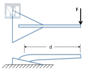
The challenge was to assume the following loading (See Fig. 1):
- The shank modeled as a cantilever beam clamped at one end and free at other.
- The load applied laterally – perpendicular to shank.
- Calculate the Force (F) required to initiate yield (bending) in shank.
Typically, while using an anchor, the load would be applied parallel, in-line, with the shank (See Fig. 2). With wind shifts, the boat may pull from side-to-side imparting an off-axis component. The anchor shank should be designed to safely accommodate this on a daily basis. Mantus Anchors uses the ABYC Standards H-40, Anchoring Mooring and Strong Holds as a basis for design loads. “Storm Anchor” loads from Table I – Design Loads for Sizing Deck Hardware are used with an appropriate Factor of Safety for design cases.
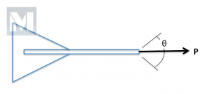
The lateral, 90-degree side load is off-nominal. In a real in-situ environment the anchor will be buried in substrate. And for anchors with thinner shanks, the arm also gets buried. This reduces the “effective” length of the shank (lever arm, d) thus making it more resistant to bending. Also, for slow-steady side loading, i.e. continuous shift to 90-degrees, the anchor will rotate and re-align itself with the load, thus increasing the axial load component (strong direction) and reducing the bending component (weak direction) – all of which significantly affect the calculated bending strength.
For the bad day when a strong sudden, 90-degree side load hits your anchor shank, it’s very important that the anchor HOLDS. Anchors that don’t set well will abruptly release, setting your boat adrift into an already bad situation. There’s also the possibility that the anchor jams in rocks or oyster beds etc. This is unfortunate and hopefully you have either the finesse to coax the anchor free or the rank to send the first mate diving.
There is no standard for side-loading capability of anchor shanks, so any individual calculation, in isolation, is not of much value. But with an array of shanks similarly assessed, a comparison can be across the different designs.
The 90-degree side load case envelopes absolute worst-case conditions:
- Shank fully unsupported.
- Load applied at end of arm.
- Fluke / shank / soil infinitely stiff
These assumptions reduce the shank model to a cantilevered beam, fixed (clamped) at one end and free at other (See Fig. 3).
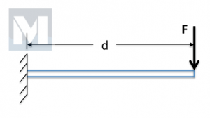
Since the output is only as good as the input. It’s important to understand the input variables – the solver used, the dimensions and material properties assigned and finally the how “yield” is defined.
All the shanks are modeled in SolidWorks and the same Finite Element Analysis (FEA/FEM) solver is used for all the shanks. The model is verified by first creating a simple model that can be solved also by closed-form solution and results compared to verify SolidWorks solver. (If interested in verification or would like to do your own using a closed form solution, see verification section at end of post.)
The shank models are all based on currently available products – dimensions and materials. Many manufactures have changed thicknesses of shanks (new models thinner) and changed materials (newer models high-tensile steel). It was too difficult to define when these changes were made for the various manufactures so this assessment was restricted to models currently available for retail. (The only exception is the Mantus Mild Steel which is no longer sold effective 9 Dec, 2013, but has been included for completeness.) Dimensions and material properties were taken from manufactures websites, or from actual anchors found at local vendors. Material properties were the most difficult to determine. Most manufactures don’t mention the specific properties on their websites. If anything is stated, it’s usually a material type – Aluminum, Stainless or High-Tensile (HT) Steel, but seldom a specific alloy or actual properties. All properties used in this assessment are shown in Table 1 below. (The Anchor ID number is shown in parentheticals next to the anchor name and correlates to its data point in Chart 1 below.) If manufacturer material properties were ambiguous, best judgment was used to define correct values. In addition, material properties are specified by manufactures to their fabricators as “minimums”, however what is delivered is typically 10-20% higher. This assessment uses the “minimum” values, hence adding to the included conservatism. Sizing is based on what the manufacturer recommends for a 40-foot sail boat, with the following exceptions: Delta recommends a 35 lb, Kobra recommends a 12.5 kg (26.5 lb) and Fortress recommends a FX-23, 15 lbs.
TABLE 1: ANCHORS AND MATERIAL PROPERTIES
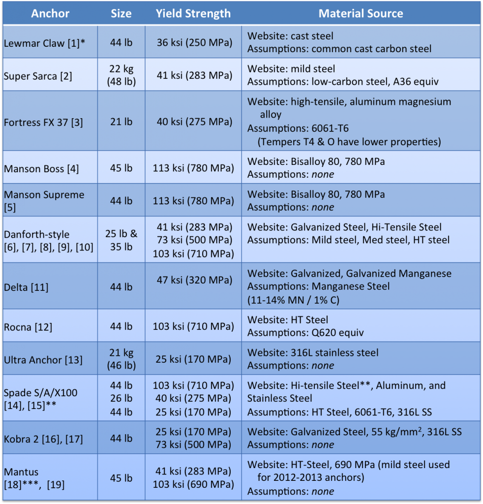
* number in parenthesis [ ] represents Anchor ID in Chart 1: Bending Strength for Laterally Loaded Shank shown below
** Spade HT-Steel not shown in chart. See Results section for explanation.
*** Mantus Mild Steel no longer available, but included for completeness.
Strength analysis can be used with high confidence to show a given structure will survive a defined load. But when trying to calculate the load at which a given structure will fail or yield, analytical methods are less accurate. Think about it like this – given a defined structure, will it yield under a 5000 lb load? Use worst-case conditions – minimum material properties, minimum material dimensions, add in a safety factor and calculate the stresses developed with an applied 5000 lb load. Are these stresses less than the minimum allowable material strength? Yes? Then it is known with very high confidence that structure will not yield with an applied 5000 lb load. In fact, in testing, it probably won’t yield with 5500 lbs or maybe even 6000 lbs because the actual dimensions are slightly thicker, because the material properties are stronger than minimums etc. Now consider the same example, except predict the load at which the structure will initiate yielding. If minimum values are used in analysis, then the failure load will be under-predicted. If max values are used, failure load will be over-predicted. If average values are used, it may be closer to truth, but unknown if over or under. So the best one can do is to use worst-case conditions (most conservative) and calculate a minimum yield strength i.e. it will always yield above this value, but it is undetermined how much above. Therefore the calculated Bending Strengths in Chart 1 below are presented as a range.
The term “yield” itself should be defined. The classic definition of “yield” is explained very well in this wiki article. But all you really need to know is “yield” is the point where the material begins to permanently deform under load. (At levels less than yield the material behaves elastically like a rubber band; greater than yield, the material deforms like stretched taffy.) Yield is not the same as Fail/Rupture/Break. For more ductile materials (i.e. mild steel) the yield point is well-defined – the point where a very linear stress-strain curve abruptly becomes non-linear. For less ductile materials (i.e. Al, Med and HT steel), it is approximated as a 0.2% offset from the linear portion of stress-strain curve.
RESULTS:
The results are presented in chart below. The HT-Steel Spade is not shown and only because its predicted Bending Strength is twice that of the highest ones shown so it falls far outside chart boundaries.
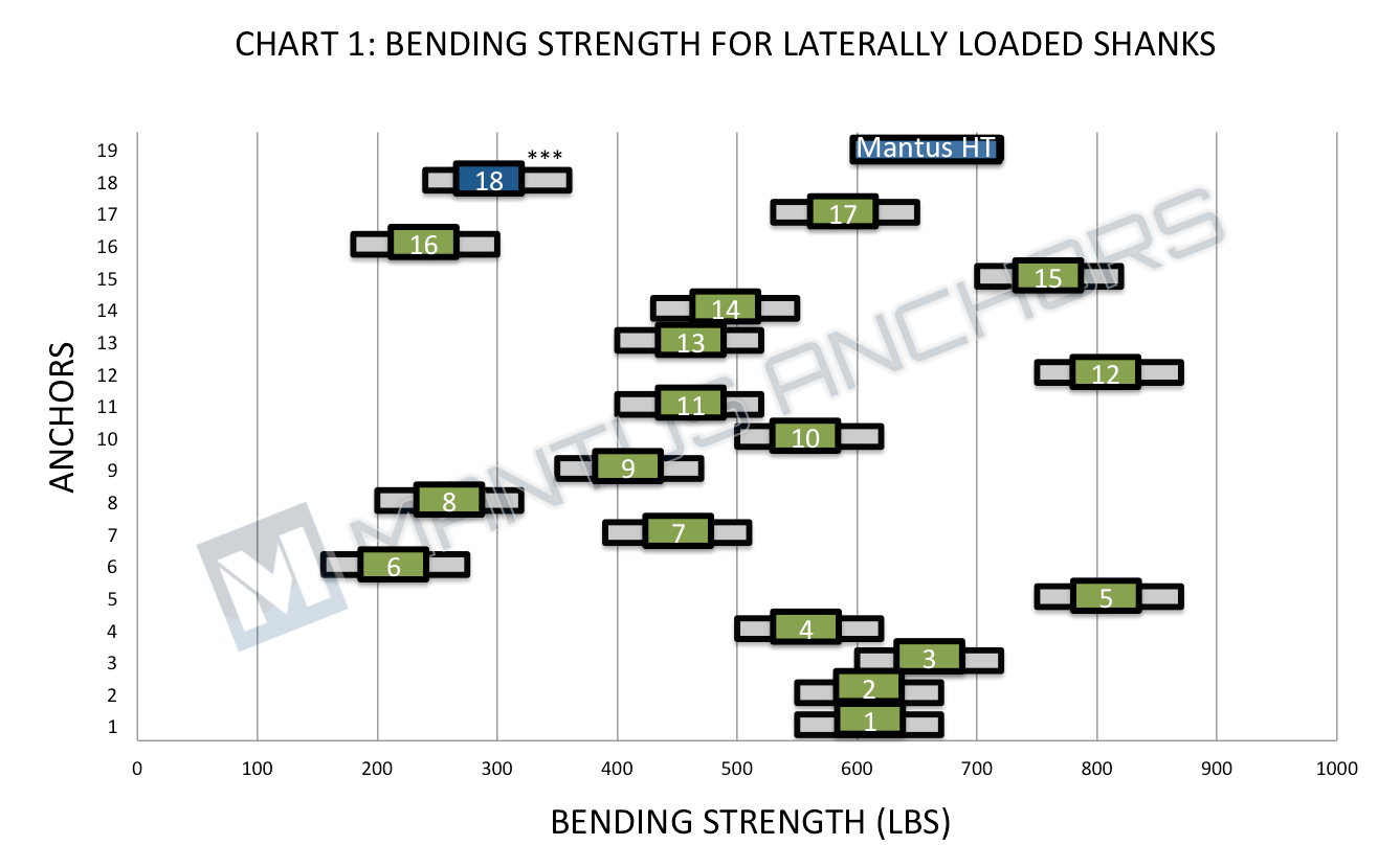
Number in [ ] represents Anchor ID in Table 1: Anchors and Material Properties above.
***[18] Mantus Mild Steel no longer available, but included for completeness.
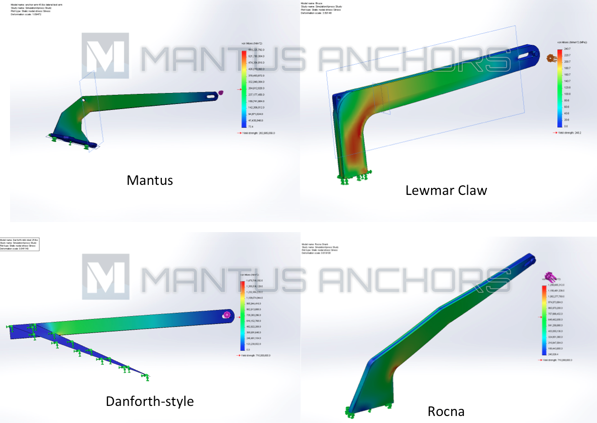
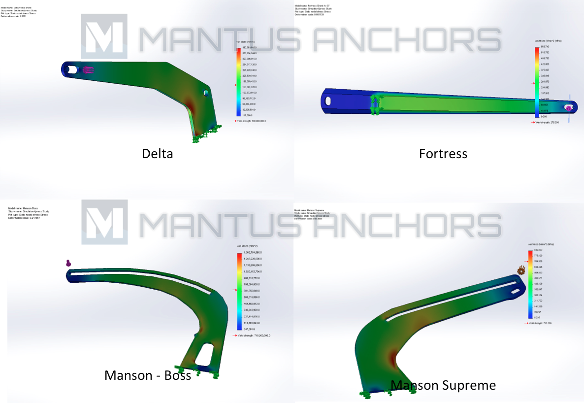
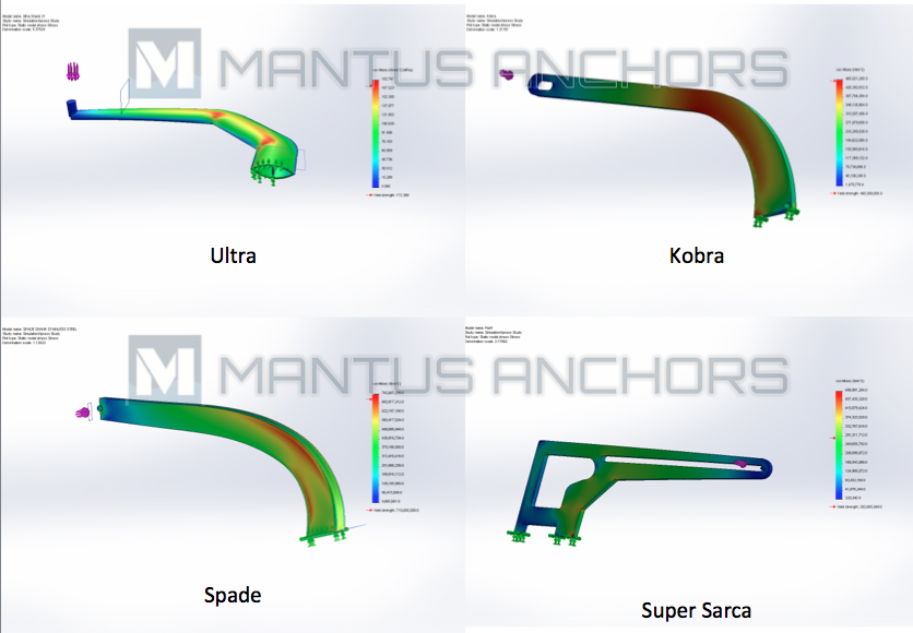
Representative FEA/FEM plots of each anchor are shown below.
VERIFICATION:
We could use a generic straight bar with random cross-section and length and defined material properties, but it is more useful to use an actual anchor and the Danforth-style works perfectly with its straight shank for this “simple” example.
The standard engineering formula for simple beam bending is:
This can be found in any Engineering Handbook or Mechanics of Materials textbook, but for the casual observer The derivation for the closed-form solution is presented clearly on wiki-Bending.
σ = Strength of bar, in this case, minimum yield allowable strength
M = bending moment = Force, F, multiplied by distance, d, (lever arm).
y = distance from neutral axis to point of interest, in our case, outer edge. Hence:
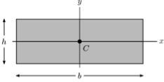
I = area moment of inertia of cross-section of interest
For a rectangular cross-section, I is given as:
where b & h are shown below.
Because of direction of applied moment, M, the appropriate I to use is Ix (see Fig. 4).
(source Wiki-Second Moment of Area)
After substituting M, I and y back into the original standard engineering formula and simplifying, one gets:
Solving for Force, F, gives:
Using the 35 lb Danforth-style anchor:
Since many different companies manufacture this type of anchor, the material strength can vary from mild steel to HT steel. Therefore the bending strength also varies:
These values compare extremely well with FEM calculated values, thereby validating the FEA/FEM modeling technique. See chart in RESULTS section above – data points 8, 9 and 10 for Mild, Med and HT Steel respectively.

