
The Anchor Bolts
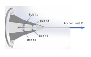
We often get questions about the “bolts” that attach the shank to the fluke. Usually a simple explanation suffices:
“You have 5/16″ chain? Well, this 35-lbs anchor has 1/2″ bolts and not one, but four of them. Each bolt is stronger than the chain that attaches to your anchor.”
But some know it’s more complicated than that…
“Yeah?, But my chain is HT.”
“OK” we reply, “So 5/16″ HT is rated for UTS of 11,700 lbs. EACH individual Grade 5 bolt has UTS of 24,000 lbs. And remember the shank/fluke is attached with FOUR bolts. Therefore the joint of a 35-lbs anchor shank has UTS of 96,000 lbs compared to the chain which has 11,700 lbs.”
Those are pretty impressive numbers and calms even the most adamant doubters, except for the couple remaining brainiacs in the crowd…
“But the load direction is not the same – chain is always in tension and these bolts see a combination of both tension and shear in most situations.”
Of course this is correct, and we do assure them that all appropriate load cases have been assessed and the bolts are generously oversized with plenty of margin. But an explanation at this level requires a bit more than a few simple facts and re-deriving the full bolt analysis on the fly is not trivial so this post is a one-stop shop addressing all questions regarding the bolts, complete with schematics and equations. For those that prefer to skip the math, I’m including summary tables too.
First for the references:
Bolts strengths for different grades are found easily on web (for example here.) I have reformatted it in this table for easy reference. Strengths are in lb/in2 (psi).

Bolt load allowables are shown below (in pounds, lbs) for Grade 5 and Grade 2 bolts.


THREE DIFFERENT LOAD CASES ARE ASSESSED.
1. Nominal use – load applied with 7:1 scope (combination tension/shear on bolts)
2. Prying load – load applied vertical (0:1 scope) at shank (pure tension case)
3. Certification loads – load applied as required by RINA certification standards (combination tension/shear)
LOAD CASE 1: Nominal Use
The schematic (or free-body diagram) shows load direction and reaction forces:
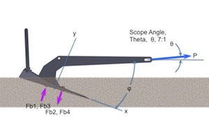
To determine Load, we refer to the ABYC Load table, “Design Loads for Sizing Deck Hardware”. These loads are known to be conservative.

Many others have performed their own testing and analysis, Robert Smith a naval architect who wrote Anchor Selection and Use and Donald Dodds, a scientist and author of Modern Seamanship and Modern Cruising Under Sail are two worth noting. Dodds has also published multiple articles regarding anchor loading in Ocean Navigator. His “Anchor Smarter” article in Jan 2003 confirms “the ABYC table overestimates anchor loads on average by a factor of 4.7. Thus Tom Hale of ABYC is right: these numbers do contain a considerable safety factor. And rightly so, for these numbers do not deal directly with dynamic loads, in the hopes that they are covered by the safety factor. Dynamic loads are commonly dealt with that way, for they are exceedingly complex.” (Dodds also has an article where he derives the effect of dynamic loads and many of his articles can be found on his North Pacific Research website in his archives section.)
OK, getting back to the calculations…
For analysis, we start with the ABYC loads – they are industry standard, despite the conservatism. And even though, the science in Smith’s and Dodds’ arguments is rock-solid and we would agree, most cruisers/sailors/boaters will never experience loads greater than what they report (1/3 – 1/4 of ABYC), as an anchor manufacturer we do not want to be the weak link or have narrow margins of safety so we take the more conservative route.
We use ABYC loads PLUS we add in a Factor of Safety of 3.
Therefore, by using our anchor sizing charts and the worse case, Storm Loads, from ABYC Table each anchor size can be mapped to a respective load. For example, in our sizing charts the correct storm anchor for a 30-ft boat is a 35-lbs anchor. (Anytime the choice is borderline, we choose the more conservative option. i.e. smaller anchor or larger load.) The Storm Load for a 30-ft boat in ABYC Table is 1400-lbs. Hence a 35-lbs anchor maps to a 1400-lbs Storm Load and this is repeated for each anchor size.
The Anchor Load is taken equivalent to Storm Load and will be referred to here on out as Anchor Load, P, as shown in figures above.
First, let’s calculate Shear because it is the easiest for this load case. The Shear Load, Ps is:
![]()
And since there are four bolts, the shear load on each individual bolts is:
For tension, there are multiple steps. First calculate the tension component directly from P (similar as shear above).
![]()
Then need to account for the down-turning Moment, M, due to the Anchor Load, P acting off-axis.
Accounting for the total of 4 bolts and adding in the tension component from the Moment, M, the Tension load on an individual bolt is:
Pm can be calculated by coupling out the Moment, M, to the bolts. Where df is the distance between fasteners (bolts).
Note the down-turning moment creates a tension component in Bolts #1 and #3, but compression in Bolts #2 and #4. So Bolts #1 and #3 are the highest loaded bolts. (BTW, this down-turning moment is also the reason why the anchor digs deeper as the load increases – a good characteristic for when squalls come through)
Once the individual shear and tension loads are calculated for each bolt, a standard interaction equation is used to calculate an overall bolt load and determine Margin of Safety, MS. (For more information on interaction equations see references: Design of Steel Structures or Threaded Fastener Strength in Combined Shear and Tension Loading)
Where Rs and Rt are the ratio of applied load to allowable load and defined as:
and
Fs and Ft are the allowables shown in the first table above, Bolt Load Allowables. Note, the Margin, MS, can be calculated against Yield (using Fty & Fsy) or Ultimate (using Ftu & Fsu).
RESULTS: The Margins are huge. For Yield Strength they vary from 500% to 800% (depending on anchor size) and for Ultimate Strength, MS varies from 700% to 1000%. (Remember this INCLUDES a Factor of Safety of 3!) In fact, these numbers are so big they are probably meaningless. (For comparison, the airplanes you fly in carry margins in the range of 1%-5%.)
However since most boaters are accustomed to looking at Working Loads, it makes more sense to calculate the Working Load for this specific Load Case and compare it to the respective Storm Load for each size anchor. (Recall, Working Load is 1/3 Ultimate Load, i.e. Factor of Safety equals 3.) Shown below are the calculated Working Loads and Ultimate Loads (with results rounded down to nearest hundred for simplification). This is an apples-to-apples comparison to the Anchor Load, P, or Storm Load from the ABYC Table.

To get an appreciation of how robust the bolt margins are, look, for example, at the 35-lbs anchor. ABYC is saying the worst case Storm Load is 1400-lbs. The Mantus Anchor with Grade 5 bolts can accommodate up to 14,900-lbs as a Working Load (44,800-lbs Ultimate). These Working loads are 7-12 times larger than the “conservative” ABYC Loads. And these are Working Loads – they include a Factor of Safety of 3 – the ultimate loads are 22-35 times larger than ABYC Loads.
The Working Loads for a Mantus Anchor with Grade 5 or Grade 2 bolts far exceeds the ABYC loads. That’s why we sleep well at night on our Mantus! 🙂
LOAD CASE 2: Prying Loads
The schematic (or free-body diagram) shows load direction and reaction forces:


The Anchor Load, P is straight up, simulating a zero scope situation. This imparts a large prying moment on the bolts due to the off-axis loading.
The solution methodology is same as Load Case 1. The only changes is the angle of applied load. The geometry is a little trickier but still very reasonable.
The new equations for the Shear, Ps, and Tension, Pt, Loads are:
![]()
![]()
Note the up-turning moment creates a tension component in Bolts #2 and #4, but compression in Bolts #1 and #3. So Bolts #2 and #4 are the highest loaded bolts.
Load Ratios and interaction equations are calculated similarly as Load Case 1.
RESULTS: The only time one would be in a zero-scope configuration would be during anchor retrieval and hopefully those loads never exceed 50-200 pounds, but nonetheless for capability comparisons, Working Loads and Ultimate Loads are shown alongside the ABYC Storm Loads for evaluation. (Note Working Loads and Ultimate Loads are again rounded down to nearest hundred for simplification.)

As before, the Working Loads have a Factor of Safety, FS = 3 included. And this “Load” is the Anchor Load, P as shown in Load Case 2 figures above. Note capability ranges from over 1000-lbs on a 25-lbs anchor to over 5,000-lbs on a 125-lbs anchor – all with a Factor of Safety, FS = 3. These Working Loads are 10% – 80% greater than ABYC Storm Loads and the Ultimate Loads are even larger.
LOAD CASE 3: Certification Requirement
RINA certifies for Super High Holding Power (SHHP) rating by utilizing the IACS (International Association of Classification Societies) Requirements Concerning Mooring, Anchoring and Towing. Strength testing is addressed by Requirement A1.4.3.3.1, Anchor Proof Testing (of SHHP Anchors) which states “The SHHP anchor is to be proof tested with the load required by Table 2 for an anchor mass equal to two times (2x) the actual mass of the SHHP anchor” and “The proof load as per Table 2 is to be applied on the arm or on the palm at a spot which, measured from the extremity of the bill, is one-third of the distance between it and the centre of the crown”. The test set-up is shown below.


<!—comment –>
(As a side note, Holding Power Testing for a SHHP anchor requires four times (4x) greater holding power than the same weight stockless anchor in same bottom conditions. Therefore, SHHP means an anchor must be as strong as a standard anchor twice its size and hold four times better than its equivalent weight standard anchor.)
The SHHP anchor is bench tested (proof tested) to a proof value for a standard anchor twice its size – i.e. 35-lbs SHHP anchor must be proof tested to levels required for a standard 70-lbs anchor. Unfortunately, the table’s smallest anchor is 50-kg (110-lbs). Which means there are no test standards for SHHP anchors weighing less than 55-lbs. These standards are written for commercial ships and are biased towards larger vessels. The IACS specification is applicable for anchors from 50-kg to 48,000-kg (105,822-lbs). Nonetheless, we can utilize the lower end of the data table to get test loads for the Mantus 65 – 125-lbs anchors. An excerpt of IACS Table 2 is shown below.
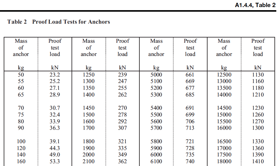
The sizes of interest are the 50 – 120-kg anchors. These applicable sizes are converted from kilogram (kg) and kiloNewton (kN) to pounds-mass and pounds-force in the table below and are mapped to an equivalent SHHP anchor size.

Test load values for the Mantus 65, 85, 105 and 125-lbs anchors can be determined by interpolating between the sizes given. It is obvious that these loads are significantly higher than the respective ABYC Storm Loads. In fact they are about 2.5 times larger. But, of course, this is because for the SHHP rating the the anchor must be tested to loads appropriate for an anchor twice its size. IACS Proof Loads for a standard anchor are a more reasonable 1.2 – 1.5 times ABYC Storm Loads.
Analytically, the bolt loads are solved using the same method for Load Case 1 and 2, except a new applied load and a new angle for theta, θ, is used. (Interestingly enough, the new angle is close to halfway between the angle for Load Case 1 and the angle for Load Case 2.
RESULTS: Equivalent Working Loads and Ultimate Loads are calculated for this specific load case. As noted before, Working Load is 1/3 of Ultimate Load – i.e. Factor of Safety equals 3 (FS=3). These Working Loads and Ultimate Loads are shown below and compared to the IACS Proof Test Load for SHHP anchors.
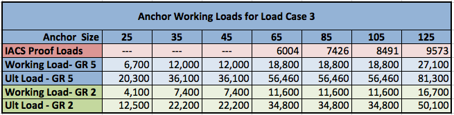
Notice that even for these very high proof loads there is still plenty of margin to the Working Loads. In most cases the Working Loads are 2-3 times higher than respective Proof Loads.
SUMMARY
For all Load Cases considered, maximum Working Loads loads exceed all Storm Loads or Proof Load conditions. This is true regardless if using Grade 2 bolts or Grade 5 bolts.
